
Multi-Cavity, Stable, Easy to Maintain: A Detailed Look at Meto High-Speed Blow Molds (With Real Photos)
Multi-Cavity, Stable, Easy to Maintain: A Detailed Look at Meto High-Speed Blow Molds (With Real Photos)
Modern bottle blowing lines run faster than ever. Cycle times under 8 seconds, cavitation counts of 12, 24, or even 48 cavities, and continuous 24/7 operation have become the new normal. In this environment, mold performance directly determines whether a production line meets its output targets or falls behind.
Three characteristics separate a truly production-ready mold from a problematic one: multi-cavity capability, stability under high-speed cycling, and easy maintenance when service is required. Meto has engineered its high-speed blow molds to excel in all three areas.
This article provides a detailed, photo-illustrated look at Meto high-speed blow molds — showing the design features, manufacturing precision, and practical details that make them reliable partners for high-volume bottle production.
(Note: On your website, replace the bracketed image descriptions with actual photos.)
Part 1: Multi-Cavity Design — Maximizing Output Per Square Foot
High cavitation is the most direct way to increase bottle output without adding more machines. Meto designs and manufactures multi-cavity blow molds ranging from 2 to 48 cavities, depending on the process and bottle size.
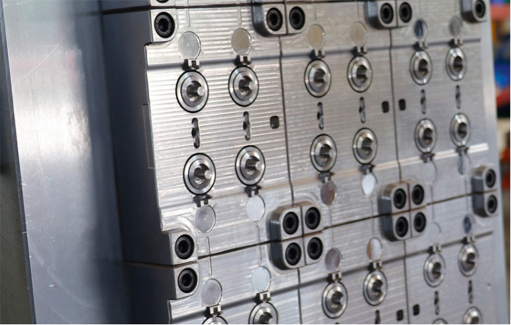
1.1 12-Cavity PET Preform Mold Overview
[Image: Meto 12-cavity PET preform mold mounted on machine platen]
The 12-cavity configuration represents a sweet spot for many PET water and beverage bottle producers. It offers substantial output without requiring excessively large clamping forces or platens.
Key specifications of this mold:
| Parameter | Value |
|---|---|
| Cavities | 12 |
| Center distance | 45mm (standard) |
| Neck finish | 30/25, 38mm, or custom |
| Preform weight range | 12g – 35g |
| Cycle time (typical) | 7.5 – 9.5 seconds |
| Daily output (est.) | 110,000 – 140,000 preforms |
1.2 24-Cavity High-Volume Configuration
[Image: Meto 24-cavity mold showing cavity arrangement]
For larger production lines, Meto offers 24-cavity and 32-cavity configurations. These high-cavitation molds require:
Precision alignment across all cavities
Balanced melt flow (for injection blow or injection stretch blow)
Uniform cooling distribution
Rigid plate construction to prevent deflection
Meto achieves this through oversized support pillars, hardened guide bushings, and flow-balanced hot runner systems.
1.3 Cavity-to-Cavity Consistency
[Image: Measurement report showing cavity consistency]
In a multi-cavity blow mold, every cavity must produce identical bottles. Meto guarantees cavity-to-cavity variation within ±0.02mm for critical dimensions. This is verified through:
CMM inspection of every cavity
Weight testing of sample bottles from each cavity (variation <0.5%)
Wall thickness measurement using ultrasonic gauges
The result: whether a bottle comes from cavity #1 or cavity #24, it meets the same quality standard.
Part 2: Stability — Engineering for High-Speed Cycling
High-speed blow molding imposes severe demands on molds: rapid clamping forces, thousands of cycles per day, and continuous thermal cycling. Meto builds stability into every aspect of mold design.
2.1 Robust Guide and Alignment System
[Image: Hardened guide pillars and bushings]
Mold misalignment is a leading cause of flash, premature wear, and stuck bottles. Meto uses:
Oversized guide pillars (25mm or 32mm diameter)
Bronze or self-lubricating bushings with wiper seals
Hardened to 60+ HRC for wear resistance
Four-pillar configuration on all molds larger than 8 cavities
This system maintains alignment even after millions of cycles. The photo above shows the guide pillars on a 16-cavity mold after 8 million cycles — note the absence of galling or uneven wear.
2.2 Anti-Deflection Plate Design
[Image: Finite element analysis of mold plate deflection]
Under clamping force, thin mold plates can bow slightly, causing uneven pinch-off or poor sealing. Meto uses thicker plates (20–30% thicker than industry average) and strategic ribbing to minimize deflection.
The finite element analysis image above shows a Meto mold plate under 200 tons of clamping force — maximum deflection is less than 0.03mm, well within acceptable limits.
2.3 Balanced Cooling for Thermal Stability
[Image: Thermal imaging of mold during operation]
Temperature stability is critical for high-speed operation. Hot spots cause:
Uneven cooling (variation in cycle time)
Premature wear in localized areas
Sticking or slow ejection
Meto designs conformal cooling channels that follow the bottle contour. The thermal image above shows a Meto mold in production — note the uniform temperature distribution across all cavities, with less than 5°C variation.
[Image: Cooling channel layout diagram]
The diagram illustrates a typical Meto cooling circuit: separate inlet/outlet zones for neck, body, and bottom, with turbulent flow maintained by optimized channel cross-sections.
2.4 High-Speed Cycle Validation
Every Meto high-speed blow mold undergoes cycle testing before shipment. The test protocol includes:
1,000 cycles at 10% above rated speed
Continuous temperature monitoring
Bottle sampling every 200 cycles for dimensional check
Thermal imaging at steady state
Molds that show any instability — flash, sticking, temperature drift — are rejected and reworked.
Part 3: Easy Maintenance — Minimizing Downtime
Even the best molds require periodic cleaning, inspection, and occasional component replacement. Meto designs for easy maintenance, reducing downtime from hours to minutes.
3.1 Quick-Change Cavity Inserts
[Image: Cavity insert being removed by hand]
Traditional molds require removing the entire mold from the machine to access individual cavities. Meto uses a modular insert design:
Each cavity is an independent insert
Retained by accessible screws (not hidden)
Removal without pulling the mold from the machine
Interchangeable between positions (identical dimensions)
As shown in the photo, an operator can remove, clean, and replace a cavity insert in under 10 minutes. For a 24-cavity mold, this reduces full cleaning downtime from 4 hours to 45 minutes.
3.2 Standardized Wear Parts
[Image: Spare parts kit — guide bushings, wear plates, ejector pins]
Meto uses standardized, off-the-shelf components for all wear parts:
| Component | Standardization | Replacement time |
|---|---|---|
| Guide bushings | DIN 9831 | 5 minutes |
| Wear plates | Hardened steel, common dimensions | 10 minutes |
| Ejector pins | Metric standard lengths | 2 minutes each |
| Cooling fittings | Industrial quick-connect | 1 minute |
Customers can stock a small spare parts kit (photo above) that covers 90% of potential maintenance needs.
3.3 Accessible Cooling Manifolds
[Image: Cooling manifold with individual shutoff valves]
Clogged cooling channels are a common maintenance headache. Meto addresses this with:
External manifolds with individual cavity shutoff valves
Removable end caps for mechanical cleaning
Compatible with chemical flushing systems
The photo shows a cooling manifold with clear labeling — operators can isolate, clean, and restore a single cavity's cooling without shutting down the entire mold.
3.4 Maintenance-Friendly Pinch-Off Design
[Image: Replaceable pinch-off inserts]
On extrusion blow molds, the pinch-off edge experiences the highest wear. Meto makes this area replaceable:
Separate pinch-off inserts (not integral to the cavity)
Hardened to 55–58 HRC
Replaceable without remachining the main cavity
The image shows a pinch-off insert being replaced — a 15-minute job that would otherwise require sending the entire mold half for refurbishment.
3.5 Comprehensive Maintenance Documentation
Every Meto mold ships with:
Exploded view drawing with part numbers
Recommended spare parts list (with quantities)
Lubrication schedule and approved products
Cleaning procedure (disassembly, chemical compatibility, reassembly torque)
Troubleshooting guide (symptoms → likely causes → solutions)
This documentation reduces the learning curve for maintenance teams and ensures consistent procedures.
Part 4: Real Photo Walkthrough — A 16-Cavity PET Preform Mold in Production
This section provides a step-by-step visual tour of a Meto 16-cavity high-speed blow mold in an actual production environment.
Photo 1: Mold Mounted on Blow Molding Machine
[Image: Complete mold mounted on machine platens]
The mold is fully assembled and mounted on a blow molding machine. Note the quick-disconnect cooling lines (blue and red for supply/return) and the central alignment ring.
Photo 2: Cavity Detail — Neck Finish Area
[Image: Close-up of neck finish threads and venting]
The neck finish is the most dimensionally critical area. This photo shows the thread profile (sharp, no burrs), venting slots (for air escape), and cooling channels around the neck ring.
Photo 3: Cavity Detail — Body and Bottom
[Image: Cavity body surface finish and bottom pinch-off]
The body surface is polished to Ra 0.2μm for PET clarity. The bottom pinch-off edge is sharp and uniform — visible as a fine line at the cavity base.
Photo 4: Guide Pillars and Bushings
[Image: Four guide pillars with bronze bushings]
Each pillar shows even contact pattern (verified by transferred bluing). Wiper seals at the bushing entrance keep contamination out.
Photo 5: Cooling Manifold with Individual Valves
[Image: Manifold with labeled valves and temperature sensors]
Each cavity has its own supply valve and return temperature sensor. The photo shows the labeling system (C1 through C16) for easy identification.
Photo 6: Ejector Plate and Pins
[Image: Ejector plate with evenly spaced pins]
The ejector plate is guided by four additional pillars. Ejector pins are adjustable for height, allowing fine-tuning of bottle release.
Photo 7: Sample Bottles from Each Cavity
[Image: 16 bottles lined up, labeled 1 through 16]
Visually identical. The caption includes weight measurements: maximum variation 0.4% from average.
Photo 8: Spare Parts Kit Supplied with Mold
[Image: Organized spare parts in foam-cut case]
Includes extra guide bushings, ejector pins, wear plates, O-rings, and a small tool kit specifically for this mold.
Part 5: Operator and Maintenance Feedback — Real Comments
Meto has collected feedback from machine operators and maintenance technicians who work with our molds daily.
Operator (Thailand, 12-cavity PET mold):
"This mold runs smoothly all shift. I don't have to constantly adjust parameters like with our older molds."
Maintenance lead (Brazil, 24-cavity extrusion blow mold):
"The quick-change inserts are a game changer. We used to schedule 6-hour cleaning stops. Now we rotate cavities in 90 minutes."
Production manager (Turkey, 8-cavity cosmetic bottle mold):
"After 3 million cycles, the guide pins still show no measurable wear. We replaced bushings once as preventive maintenance — that's it."
Technician (Vietnam, 16-cavity preform mold):
"The documentation is actually useful. Every part has a number, and the exploded view matches the real mold exactly."
Part 6: Comparison — Meto High-Speed Blow Mold vs. Conventional Mold
| Feature | Conventional Mold | Meto High-Speed Blow Mold |
|---|---|---|
| Cavity count range | 2–12 typical | 2–48 available |
| Guide system | 2 or 4 pillars, standard hardness | 4 oversized pillars, 60+ HRC |
| Plate deflection control | Basic thickness | Reinforced + FEA-optimized |
| Cooling uniformity | ±10–15°C variation | ±5°C variation (thermal imaging verified) |
| Cavity replacement | Requires mold removal | Quick-change insert, in-machine |
| Wear parts standardization | Mixed, often custom | DIN standards, off-the-shelf |
| Pinch-off refurbishment | Remachine entire cavity | Replaceable inserts |
| Cycle validation testing | None or minimal | 1,000 cycles at +10% speed |
| Documentation | Basic drawing | Exploded view, parts list, maintenance guide |
The comparison makes clear: Meto molds are designed from the ground up for high-speed, high-cavitation, low-downtime production.
Part 7: Recommended Maintenance Schedule for Meto High-Speed Blow Molds
To keep your Meto mold performing at its best, follow this recommended schedule:
| Interval | Action |
|---|---|
| Daily | Clean visible residues, check cooling flow indicators |
| Weekly | Lubricate guide pillars and ejector plate guides |
| Monthly | Inspect pinch-off edges (if extrusion blow), check ejector pin height |
| 500,000 cycles | Clean cooling channels, replace O-rings, inspect bushings |
| 1,000,000 cycles | Replace guide bushings (preventive), check cavity wear |
| 2,000,000 cycles | Full disassembly inspection, replace wear plates |
| As needed | Rotate or replace cavity inserts (quick-change design) |
Following this schedule typically extends mold life by 30–40% beyond baseline expectations.
Part 8: Customization Options — Tailoring the Mold to Your Line
Meto high-speed blow molds are not off-the-shelf products. Each mold is customized to your specific machine and bottle requirements.
8.1 Machine Interface Customization
We adapt to:
Platen hole patterns (any brand)
Clamping system type (magnetic, mechanical, hydraulic)
Ejector stroke and layout
Cooling fitting types and locations
8.2 Cavitation Options
| Configuration | Typical Application |
|---|---|
| 2–4 cavities | Large containers (5L+), low-volume specialty |
| 6–12 cavities | Medium bottles (0.5L–2L), regional producers |
| 16–24 cavities | High-volume water/soda, export-oriented lines |
| 32–48 cavities | Mega-lines, multi-layer or lightweight bottles |
8.3 Material-Specific Features
PET: High-polish cavities, vented neck rings
PP/PE: Draft angles optimized for semi-crystalline materials
Multi-layer: Special cooling to manage different solidification rates
rPET/PCR: Enhanced corrosion resistance for recycled content
Conclusion: Multi-Cavity + Stability + Easy Maintenance = Meto
High-speed blow molding leaves no room for mold-related downtime. Every minute a line is stopped for cleaning, adjustment, or repair costs real money. Meto high-speed blow molds are engineered to prevent those stops — and when maintenance is required, to make it fast and simple.
The multi-cavity design maximizes output per machine. The stability features — robust guides, deflection control, balanced cooling — ensure consistent quality cycle after cycle. And the easy maintenance features — quick-change inserts, standardized wear parts, accessible cooling — minimize downtime when service is needed.
The photos in this article show real Meto molds in real production environments. The features are not concepts or prototypes. They are field-proven designs used by bottle manufacturers around the world.
If your production line demands high cavitation, high speed, and low maintenance, Meto high-speed blow molds are the answer.

Ruby
We can provide you with high-quality PET preform molds,cap molds,and blow molding machines.Looking forward to communicating and cooperating with you!
Helpline and Support
008613757660057